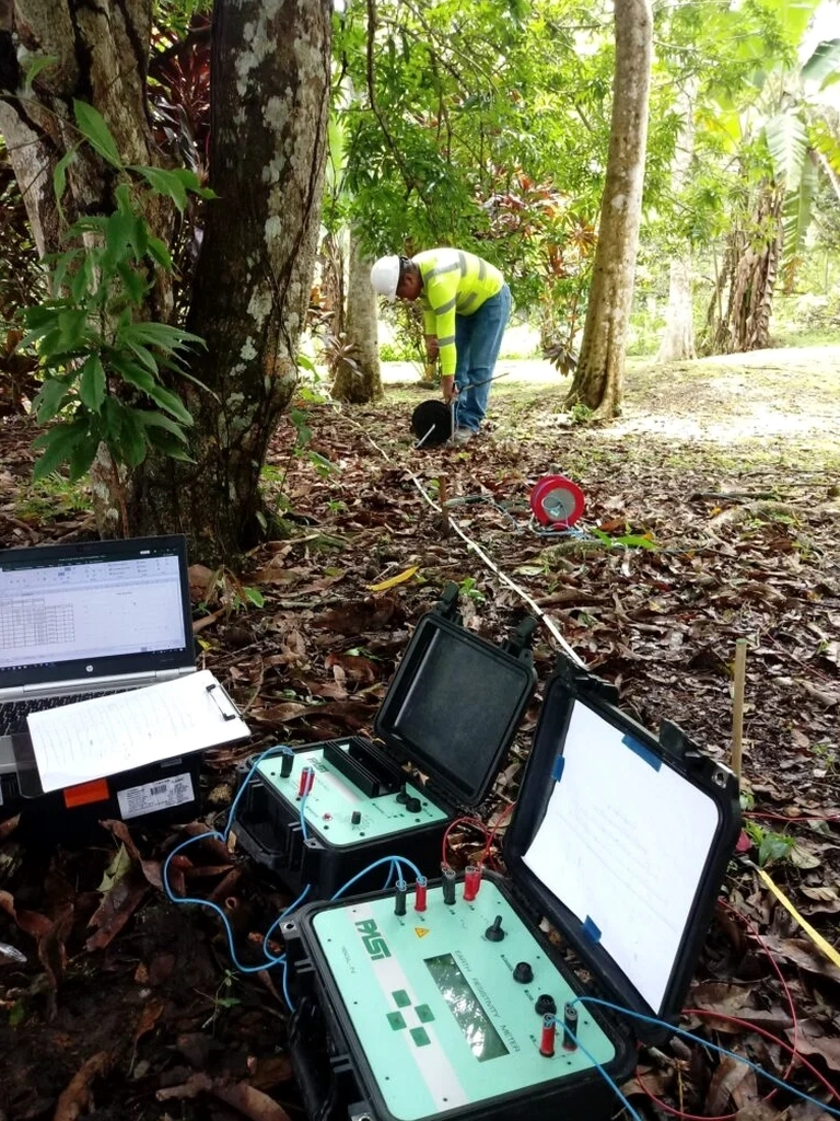
Markham’s rapid expansion north of Highway 7 often encounters the complex Oak Ridges Moraine deposits. These interlayered silts, sands, and tills create subsurface conditions that change dramatically over short distances. Standard borehole programs sometimes miss the lateral transitions that matter for foundation design. Electrical resistivity testing fills that gap. A Vertical Electrical Sounding (VES) deploys a Schlumberger array to map vertical resistivity profiles without disturbing the ground. The method proves valuable across the Rouge River watershed, where paleochannels and buried valleys hide beneath the glacial drift. Our field crew runs the ABEM Terrameter LS2 with a 400-meter maximum spread, resolving layers down to 60 meters depth. The resistivity contrast between saturated granular soils and the underlying till aquitard is usually sharp in Markham—often exceeding 50 ohm-m. That signature helps delineate groundwater pathways before a single bucket hits the ground. Complementing resistivity data with a test pit investigation validates layer boundaries where access permits, and a grain size analysis calibrates the geophysical signature against actual gradation.
Resistivity contrasts across the Halton Till–glaciofluvial sand interface typically exceed 40 ohm-m in Markham—an unambiguous marker for mapping the aquitard.
Local ground factors
Much of Markham east of McCowan Road sits on glaciolacustrine clays that can host perched water tables. These conditions create a risk of misidentifying a temporary saturation lens as a regional aquifer. The consequence is expensive over-design of dewatering systems or, worse, a flooded excavation in November when the water table peaks. A VES survey reduces that uncertainty. The resistivity contrast between silt and saturated sand is clear, but clay layers with high cation-exchange capacity can produce low-resistivity false positives—a nuance the field geophysicist must flag. In the Bur Oak and Mount Joy areas, rapid urban development has also introduced buried fill and former drainage courses now invisible at the surface. Resistivity profiles readily detect these anomalies as low-resistivity linear features, giving the geotechnical team early warning before shoring design begins.
Frequently asked questions
What is the typical cost of a VES survey in Markham?
A single Vertical Electrical Sounding station with interpretation typically ranges from CA$790 to CA$1,300, depending on the maximum investigation depth and the electrode spread length. A full 2D ERT line with multiple soundings is priced per linear meter; we provide a fixed quote after reviewing your site plan and investigation objectives.
How deep can resistivity testing reach in Markham glacial deposits?
With a 400-metre maximum electrode spread, the ABEM Terrameter LS2 can resolve layers down to approximately 60 metres below grade. The actual depth of investigation depends on the subsurface resistivity contrast; the silty sand and clay sequences common in Markham generally permit reliable signal penetration to 40–60 metres.
Can you perform resistivity surveys on paved surfaces?
Yes. We use sponge-contact electrodes that require only a small amount of water to couple with asphalt or concrete. This method works well in Markham’s industrial parks and along roadways without coring or damaging the pavement.
How do you validate the resistivity interpretation?
We calibrate resistivity profiles against direct geotechnical data. A nearby CPT sounding or test pit provides lithologic ground truth, and grain-size analysis on recovered samples confirms the silt, sand, or clay fractions corresponding to each resistivity range. This integrated approach reduces interpretation uncertainty to under 5 percent RMS error.